


Achieving proper alignment by detecting and correcting soft foot
Proper alignment of direct-coupled machinery is an essential element in reliability of a new or repaired machine (motor, pump, gear case, etc.). One common impediment to achieving proper alignment and smooth operation is a “soft foot” condition.
A soft foot occurs when all the feet of a machine case do not sit flat on the supporting base so that tightening the foot bolts causes distortion of the machine case. The source of the soft foot could be a baseplate which is not flat or machine feet which are distorted. Not only does this make it difficult to align the machine, but the casing distortion may add additional load to the bearings and create internal misalignment between the rotating and stationary elements of the machine resulting in poor performance and increased vibration.
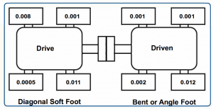
The most common instances of soft foot occur with four-footed electric motors. There are two general categories of soft foot; non-coplanar feet and individual feet that are not flat (see Figure 1). The second of those categories include feet that have corrosion damage. Corrosion damage cannot be corrected by shimming; feet with significant corrosion damage must be re-machined to avoid the consequences of a soft foot condition. Feet that are bent or at an angle to the foot plane can to some degree be corrected with proper shimming (see Figure 2 for limits). The first category, non-coplanar feet, can generally be corrected with proper shimming.
 |
 |
Detecting soft foot
There are a number of methods to detect a soft foot condition, and suitable methods should be employed in the course of any machine installation. Since common tests for soft foot use the same tools used for shaft alignment, it is convenient to test for soft foot as part of the shaft alignment procedure. However, perhaps the best test for soft foot is to insert feeler gauges between each foot and base foot pad. This test can be done without setting up shaft alignment instruments or indicators and is a recommended practice whenever a machine case is set in place.
” A soft foot occurs when all the feet of a machine case do not sit flat on the supporting base so that tightening the foot bolts causes distortion of the machine case. The source of the soft foot could be a baseplate which is not flat or machine feet which are distorted. Not only does this make it difficult to align the machine, but the casing distortion may add additional load to the bearings and create internal misalignment between the rotating and stationary elements of the machine resulting in poor performance and increased vibration·,,
When using shaft alignment instrument or dial indicator setups to detect soft foot, the general approach is to have all feet bolts tight, then loosen only one foot bolt and see what movement is indicated on the shaft alignment indicators. Dial indicators and some laser systems only indicate in a single plane (vertical or horizontal) so the vertical plane is the preferred plane to monitor for soft foot tests.
Laser systems that indicate in both planes simultaneously give a slightly better indication of movement when the foot bolt is loosened. The common procedure is to loosen a single foot bolt, observe the indicated movement, then re-tighten the bolt and move to the next foot until each foot has been tested.
Some alignment technicians prefer to not re-tighten the bolt, but instead successively loosen each bolt observing the total indicated movement. They may then reverse the procedure and successively tighten each bolt until all are secured, while observing the indicated movement. This extended procedure gives a good indication of how a soft foot condition might affect the alignment process.
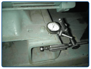
While this procedure of using shaft mounted alignment indicators to test for soft foot may provide a reasonably accurate indication of whether a soft foot condition is present, it should not be used to attempt to correct a soft foot. Rather, manual testing with a dial test indicator mounted at each foot provides a much more effective and efficient means of correcting soft foot. See Figure 3. The dial test indicator is mounted to the foundation and set to indicate upward movement of the foot as the foot bolt is loosened (all foot bolts tight). An upward movement of the foot greater than 0.002″ (0.05 mm) indicates a soft foot condition that should be corrected. The foot bolt is re-tightened and the test repeated for each foot bolt.
Correcting soft foot
The most common soft foot indications are of two diagonal feet being soft, or of a single foot being soft. These generally indicate two different types of soft foot. Diagonal soft feet tend to indicate a short foot (feet are flat but not coplanar). A single soft foot tends to result from a bent or angled foot. Correcting a short foot is pretty straightforward; correcting a bent or angled foot is more complex.
To correct a short foot (diagonal feet are soft), tighten only the two diagonal feet that were not soft, leaving the soft feet bolts loose. Remove all shims from those two feet. Use feeler gauges between the soft feet and the base foot pad to determine the amount of shims required for each of the two soft feet. Place the required shims and retest for soft foot.
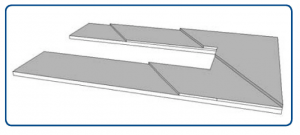
When testing indicates a single soft foot, suspect that the foot is bent or angled. Leave only that foot loose. Then remove all shims and use feeler gauges to determine the amount of shims required to correct the soft foot. Care must be taken to profile the gap: measure in from each side as well as the front and back of the foot to the bolt hole. For a bent or angled foot, the variation of gap will indicate the direction of the angle. Stepped or staggered shims must be fashioned to match the profile of the gap (see Figure 4). No more than five steps should be used and no more than 0.015″ (0.38 mm) total gap variation should be corrected with shims. Feet with greater than 0.015″ (0.38 mm) variation in gap should be straightened or re-machined to correct the angle condition.
General recommendations for shims
The area of the shim should not be smaller than 80 percent of the area of the foot. It is recommended to accurately measure the thickness of shims that are greater than 0.020″ (0.51 mm). It is also recommended to accurately measure the entire shim stack to verify total thickness.
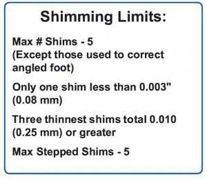
No more than five total shims shall be placed under any machine case foot, excluding the shims to correct angle foot conditions. No more than one of those shims should be less than 0.003″ (0.08 mm) thickness. The sum of the three thinnest shims should be 0.010″ (0.25 mm) or greater.
No more than five stepped shims should be used to correct soft foot between a machine case foot and base plate or foundation. Shims may only be stepped in a single direction.
Proper attention to detecting and correcting soft foot conditions on new or repaired machine installations will save time in achieving proper shaft alignment, prevent frame or casing distortion that reduces machine reliability and efficiency, and avoid increased vibration levels.